Double acting pneumatic actuator
OMAL DA Größen von DA 8 bis DA 480
Double acting pneumatic actuator
DIN/ISO 5211 DIN 3337
| Dimensions 1 | ||||||||||||||
|---|---|---|---|---|---|---|---|---|---|---|---|---|---|---|
| Größe | L | L1 | A | B | X | C | D | E | U | G | H | N | ØM | |
| > | mm | mm | mm | mm | mm | mm | mm | mm | mm | mm | mm | mm | mm | |
| DA 8 | F03 | 70 | - | 59,70 | 42,70 | 43,20 | 35,00 | 24,70 | 9 | 9,50 | 8 | 8 | 15 | - |
| DA 15 | F03 | 114 | 160 | 74,40 | 52,00 | 48,00 | 44,20 | 30,20 | 9 | 10,20 | 8 | 10 | 20 | M 5x10 |
| DA 30 | F03 | 130 | 177 | 82,00 | 60,00 | 55,00 | 47,50 | 34,50 | 9 | 10,20 | 9 | 10 | 20 | M 5x6 |
| DA 45 | F04 | 144 | 190 | 88,00 | 65,70 | 60,00 | 50,00 | 38,00 | 11 | 13,20 | 10 | 13 | 20 | M 5x6 |
| DA 60 | F04 | 152 | 198 | 92,00 | 70,00 | 65,00 | 52,50 | 39,50 | 11 | 12,20 | 10 | 13 | 20 | M 5x6 |
| DA 90 | F05 | 169 | 235 | 101,00 | 77,50 | 72,00 | 56,50 | 44,50 | 14 | 16,30 | 12 | 13 | 20 | M 5x6 |
| DA 120 | F05 | 184 | 250 | 119,00 | 86,00 | 80,00 | 70,00 | 49,00 | 14 | 16,30 | 12 | 13 | 30 | M 5x6 |
| DA 180 | F07 | 212 | 279 | 129,00 | 96,00 | 90,00 | 75,00 | 54,00 | 17 | 19,30 | 15 | 16 | 30 | M 5x6 |
| DA 240 | F07 | 255 | 341 | 139,00 | 106,00 | 100,00 | 80,00 | 59,00 | 17 | 19,30 | 15 | 17 | 30 | M 5x6 |
| DA 360 | F10 | 264 | 350 | 151,00 | 118,00 | 112,00 | 86,00 | 65,00 | 22 | 24,50 | 19 | 19 | 30 | M 5x6 |
| DA 480 | F10 | 295 | 381 | 163,00 | 130,00 | 124,00 | 92,00 | 71,00 | 22 | 24,50 | 19 | 19 | 30 | M 5x6 |
| Dimensions 2 | |||||||||||||
|---|---|---|---|---|---|---|---|---|---|---|---|---|---|
| Größe | Ø0 | P | Q | R | S | T | ØV | ØK | F | ØY | Z | Luft | |
| mm | mm | mm | mm | mm | mm | mm | mm | mm | mm | dm3 | kg | ||
| DA 8 | F1/8" | 11,50 | 30 | 23,00 | 5 | - | 36 | 25 | 2 | M 5x8 | - | 0,016 | 0,29 |
| DA 15 | 1/8" | 9,00 | 80 | 20,50 | 6 | 70 | 36 | 25 | 2 | M 5x9 | 30 | 0,06 | 0,73 |
| DA 30 | 1/8" | 12,00 | 80 | 25,00 | 0 | 70 | 36 | 25 | 2 | M 5x9 | 36 | 0,12 | 1,00 |
| DA 45 | 1/8" | 12,50 | 80 | 25,00 | 0 | 70 | 42 | 30 | 2 | M 5x9 | 36 | 0,18 | 1,25 |
| DA 60 | 1/8" | 17,90 | 80 | 20,50 | 0 | 70 | 42 | 30 | 2 | M 5x9 | 36 | 0,25 | 1,56 |
| DA 90 | 1/8" | 17,90 | 80 | 20,50 | 0 | 70 | 50 | 35 | 3 | M 6x11 | 36 | 0,36 | 1,85 |
| DA 120 | 1/8" | 121,00 | 80 | 25,00 | 0 | 70 | 50 | 35 | 3 | M 6x11 | 36 | 0,50 | 2,80 |
| DA 180 | 1/8" | 21,00 | 80 | 25,00 | 0 | 70 | 70 | 55 | 3 | M 8x15 | 36 | 0,72 | 3,40 |
| DA 240 | 1/8" | 26,00 | 80 | 25,00 | 0 | 70 | 70 | 55 | 3 | M 8x15 | 36 | 1,00 | 5,90 |
| DA 360 | 1/8" | 25,00 | 80 | 25,00 | 0 | 70 | 102 | 70 | 3 | M 10x17 | 36 | 1,45 | 7,20 |
| DA 480 | 1/8" | 32,00 | 80 | 25,00 | 0 | 70 | 102 | 70 | 3 | M 10x17 | 36 | 2,00 | 9,95 |
Technical features
Mounting flange according to DIN/ISO 5211 DIN 3337 F03 - F04 - F05 - F07 - F10 - F12 - F14.
NAMUR connection for accessories.
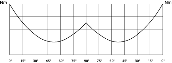
Rotation angle: 90°
Torque: directly proportional to the air supply (see table)
The code numbers after the DA letters always correspond to the breakaway torque in Nm by 5.6 bar air supply
Working condition
Temperature: from 0°C to +80°C; from -20°C to +80°C with dry air only.
Air supply: 5,6 bar; maximum 8,4 bar.
Operating media: dry filtered air, not necessary lubricated. In case of lubricated air, either non detergent oil or NBR-compatible oil must be used.
| Drehmoment in Nm/Output Torque Table (Nm) | α° = Drehwinkel/Rotation angle | |||||||
| Größe/Size | α° | 3 bar | 4 bar | 5 bar | 5,6 bar | 6 bar | 7 bar | 8 bar |
| DA 8 | 0° | 4,3 | 5,7 | 7,1 | 8,0 | 8,6 | 10,0 | 11,4 |
| 45° | 2,1 | 2,8 | 3,6 | 4,0 | 4,3 | 5,0 | 5,7 | |
| 90° | 4,3 | 5,7 | 7,1 | 8,0 | 8,6 | 10,0 | 11,4 | |
| DA 15 | 0° | 8,0 | 10,7 | 13,4 | 15,0 | 16,1 | 18,8 | 21,4 |
| 50° | 4,0 | 5,4 | 6,7 | 7,5 | 8,0 | 9,4 | 10,7 | |
| 90° | 6,0 | 8,1 | 10,1 | 11,3 | 12,1 | 14,1 | 16,1 | |
| DA 30 | 0° | 16,1 | 21,4 | 26,8 | 30,0 | 32,1 | 37,5 | 42,9 |
| 50° | 8,0 | 10,7 | 13,4 | 15,0 | 16,1 | 18,8 | 21,4 | |
| 90° | 12,0 | 16,1 | 20,1 | 22,5 | 24,1 | 28,1 | 32,1 | |
| DA 45 | 0° | 24,0 | 32,1 | 40,2 | 45,0 | 48,3 | 56,4 | 64,2 |
| 50° | 12,0 | 16,2 | 20,1 | 22,5 | 24,0 | 28,2 | 32,1 | |
| 90° | 18,0 | 24,3 | 30,3 | 34,0 | 36,3 | 42,3 | 48,3 | |
| DA 60 | 0° | 32,1 | 42,9 | 53,6 | 60,0 | 64,3 | 75,0 | 85,7 |
| 50° | 16,1 | 21,4 | 26,8 | 30,0 | 32,1 | 37,5 | 42,9 | |
| 90° | 24,1 | 32,1 | 40,2 | 45,0 | 48,2 | 56,3 | 64,3 | |
| DA 90 | 0° | 48,0 | 64,2 | 80,4 | 90,0 | 96,6 | 112,8 | 128,4 |
| 50° | 24,0 | 32,4 | 40,2 | 45,0 | 48,0 | 56,4 | 64,2 | |
| 90° | 36,0 | 48,6 | 60,6 | 68,0 | 72,6 | 84,6 | 96,6 | |
| DA 120 | 0° | 64,3 | 85,7 | 107,1 | 120,0 | 128,6 | 150,0 | 171,4 |
| 50° | 32,1 | 42,9 | 53,6 | 60,0 | 64,3 | 75,0 | 85,7 | |
| 90° | 48,2 | 64,3 | 80,4 | 90,0 | 96,4 | 112,5 | 128,6 | |
| DA 180 | 0° | 96,0 | 128,4 | 160,8 | 180,0 | 193,2 | 225,6 | 264,8 |
| 50° | 48,0 | 64,8 | 80,4 | 90,0 | 96,0 | 112,8 | 128,4 | |
| 90° | 72,0 | 97,2 | 121,2 | 135,0 | 145,2 | 169,2 | 193,2 | |
| DA 240 | 0° | 128,6 | 171,4 | 214,3 | 240,0 | 257,1 | 300,0 | 342,9 |
| 50° | 64,3 | 85,7 | 107,1 | 120,0 | 128,6 | 150,0 | 171,4 | |
| 90° | 96,4 | 128,6 | 160,7 | 180,0 | 192,9 | 225,0 | 257,1 | |
| DA 360 | 0° | 192,0 | 256,8 | 321,6 | 360,0 | 386,4 | 451,2 | 513,6 |
| 50° | 96,0 | 129,6 | 160,8 | 180,0 | 192,0 | 225,6 | 264,8 | |
| 90° | 144,0 | 194,4 | 242,4 | 270,0 | 290,4 | 338,4 | 286,4 | |
| DA 480 | 0° | 257,1 | 342,9 | 428,6 | 480,0 | 514,3 | 600,0 | 685,7 |
| 50° | 128,6 | 171,4 | 214,3 | 240,0 | 257,1 | 300,0 | 342,9 | |
| 90° | 192,9 | 257,1 | 321,4 | 360,0 | 385,7 | 450,0 | 514,3 | |
| DA 720 | 0° | 384,0 | 513,6 | 643,2 | 720,0 | 772,8 | 902,4 | 1027,2 |
| 50° | 192,0 | 259,2 | 321,6 | 360,0 | 384,0 | 451,2 | 529,6 | |
| 90° | 288,0 | 388,8 | 484,8 | 540,0 | 580,8 | 676,8 | 772,8 | |
| DA 960 | 0° | 514,3 | 685,7 | 857,1 | 960,0 | 1028,6 | 1200,0 | 1371,4 |
| 50° | 257,1 | 342,9 | 428,6 | 480,0 | 514,3 | 600,0 | 685,7 | |
| 90° | 385,7 | 514,3 | 642,9 | 720,0 | 771,4 | 900,0 | 1028,6 | |
| DA 1440 | 0° | 768,0 | 1027,2 | 1286,4 | 1440,0 | 1545,6 | 1804,8 | 2057,4 |
| 50° | 384,0 | 518,4 | 643,2 | 720,0 | 768,0 | 902,4 | 1059,2 | |
| 90° | 576,0 | 777,6 | 969,9 | 1080,0 | 1161,6 | 1353,6 | 1545,6 | |
| DA 1920 | 0° | 1028,6 | 1371,4 | 1714,3 | 1920,0 | 2057,1 | 2400,0 | 2742,9 |
| 50° | 514,3 | 685,8 | 857,1 | 960,0 | 1028,6 | 1200,0 | 1371,4 | |
| 90° | 771,4 | 1028,6 | 1285,7 | 1440,0 | 1542,9 | 1800,0 | 2057,1 | |
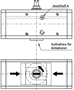
Funktionsweise
Wird Gewindebohrung A mit Luft beaufschlagt, ergibt sich eine Drehung gegen den Uhrzeigersinn. Die Zeichnung stellt die Endposition dar.
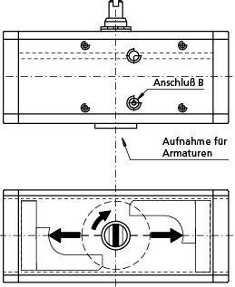
Wird Gewindebohrung B mit Luft beaufschlagt, ergibt sich eine Drehung im Uhrzeigersinn. Die Zeichnung stellt die Endposition dar.
Working plan
Supplying air through the air connection A, the pistons move towards the centre in an anticlockwise direction. The above drawing shows the final position.
Supplying air through the air connection B, the pistons move outwards in an clockwise direction. The above drawing shows the final position.
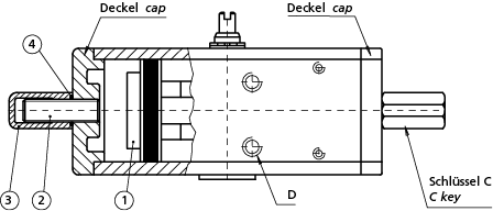
Hubeinstellung
A) Luft in die Bohrung D geben, so dass sich die Kolben (Teile Nr. 1) in der Endposition befinden.
B) Die Gegenmutter (Teile Nr. 3) abschrauben und mit
Schlüssel C justieren.
C) Die Luftzufuhr unterbrechen.
D) Mit einem Sechskantschlüssel die Schraube (Teile Nr. 2) in die gewünschte Einstellung einschrauben.
Anmerkung: Hubeinstellung höchstens 10°, von 80° bis 90°.
E) Luft in die Bohrung D einführen, prüfen dass beide Schrauben (Teile Nr.2) die Kolben berühren.
F) Die mit O-Ring (Teile Nr. 4) ausgerüstete Gegenmutter (Teile Nr. 3) einschrauben, O-Ring dichtet zwischen der Mutter und dem Deckel.
Adjustment device
A) Supply air throught the air connection D so that the pistons (part 1) move to the end stroke position, towards the caps.
B) Remove the counter nut (part 3) acting on the C key.
C) Shut off the air supply.
D) Adjust the end stroke as desired, acting on the screws (part 2) with an exagonal key.
Note: maximum adjusting stroke 10°, ranging from 80° to 90°. Other regulations on request.
E) Supply air through the air connection D and check that both screws stop the pistons.
F) Screw the counter-nut (part 3) and its o-ring (part 4) to keep nut and cap thight.