Selbstrückstellender pneumatischer Antrieb
OMAL SR Größen von SR 15 bis SR 240
Selbstrückstellender pneumatischer Antrieb
DIN/ISO 5211 DIN 3337


| Abmessungen 1 | ||||||||||||
|---|---|---|---|---|---|---|---|---|---|---|---|---|
| Größe | L | A | B | X | C | D | E | U | G | H | N | ØM |
| mm | mm | mm | mm | mm | mm | mm | mm | mm | mm | mm | mm | |
| SR 15 F03 | 221 | 82 | 60 | 55 | 47,50 | 34,50 | 9 | 10,20 | 9 | 10 | 20 | M 5x6 |
| DA 30 F04 | 240 | 92 | 70 | 65 | 52,50 | 39,50 | 11 | 12,20 | 10 | 13 | 20 | M 5x6 |
| SR 45 F05 | 294 | 101 | 77,50 | 72 | 56,50 | 44,50 | 14 | 16,30 | 12 | 13 | 20 | M 5x6 |
| SR 60 F05 | 320 | 119 | 86 | 80 | 70 | 49 | 14 | 16,30 | 12 | 13 | 30 | M 5x6 |
| SR 90 F07 | 357 | 129 | 96 | 90 | 75 | 54 | 17 | 19,30 | 15 | 16 | 30 | M 5x6 |
| SR 120 F07 | 395 | 139 | 106 | 100 | 80 | 59 | 17 | 19,30 | 15 | 17 | 30 | M 5x6 |
| SR 180 F010 | 436 | 151 | 118 | 112 | 86 | 65 | 22 | 24,30 | 19 | 19 | 30 | M 5x6 |
| SR 240 F10 | F487 | 163 | 130 | 124 | 92 | 71 | 22 | 24,30 | 19 | 19 | 30 | M 5x6 |
| Abmessungen 2 | |||||||||||||
|---|---|---|---|---|---|---|---|---|---|---|---|---|---|
| Größe | ØO | P | Q | R | S | T | ØV | ØK | F | ØY | Z | Luft | |
| mm | mm | mm | mm | mm | mm | mm | mm | mm | mm | dm3/c | kg | ||
| SR 15 | 1/8" | 12 | 80 | 25 | 0 | 70 | 36 | 25 | 2 | M 5x9 | 36 | 0,06 | 1,30 |
| SR 30 | 1/8" | 17,90 | 80 | 20,50 | 0 | 70 | 42 | 30 | 2 | M 5x9 | 36 | 0,12 | 2,00 |
| SR 45 | 1/8" | 17,90 | 80 | 25 | 0 | 70 | 50 | 35 | 3 | M 6x11 | 36 | 0,18 | 2,40 |
| SR 60 | 1/8" | 21 | 80 | 25 | 0 | 70 | 50 | 35 | 3 | M 6x11 | 36 | 0,25 | 3,50 |
| SR 90 | 1/8" | 21 | 80 | 25 | 0 | 70 | 50 | 55 | 3 | M 8x15 | 36 | 0,36 | 4,60 |
| SR 120 | 1/8" | 26 | 80 | 25 | 0 | 70 | 70 | 55 | 3 | M 8x15 | 36 | 0,50 | 7,00 |
| SR 180 | 1/8" | 25 | 80 | 25 | 0 | 70 | 102 | 70 | 3 | M 10x17 | 36 | 0,72 | 9,40 |
| SR 240 | 1/8" | 32 | 80 | 25 | 0 | 70 | 102 | 70 | 3 | M 10x17 | 36 | 1,00 | 12,80 |
Technische Eigenschaften
Montageflansch entsprechend DIN/ISO 5211 DIN 3337 F03 - F04 - F05 - F07 - F10 - F12 - F14.
NAMUR-Anschluss für Zubehör.
Drehwinkel: 90°
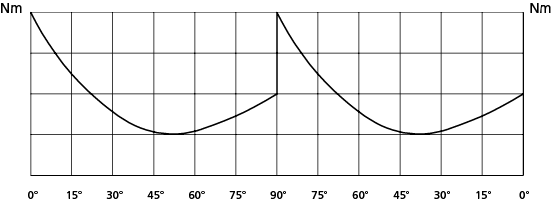
Drehmoment:
Die Drehmomentangaben beziehen sich nur auf die Federrückstellung und nicht auf die Luftbetätigung. Die Federn sind in drei verschiedenen Ausführungen erhältlich. Die Code-Nummer nach der Bezeichnung SR entspricht dem Breakaway-Drehmoment bei 5,6 bar Luftdruck.
Anforderungen
Temperatur: von 0°C bis +80°C; von -20°C bis +80°C bei trockener Luft.
Nenndruck: 5,6 bar; max. 8,4 bar.
Steuermedium: gefilterte trockene Druckluft, nicht notwendigerweise geschmiert, zur Schmierung kann nichtreinigendes Öl verwendet werden das sich mit NBR verträgt.
Technical features
Mounting flange according to DIN/ISO 5211 DIN 3337 F03 - F04 - F05 - F07 - F10 - F12 - F14.
NAMUR connection for accessories.
Rotation angle: 90°
Torque:
The return torque depends on spring action only, notwithstanding the air supply. The spring is provided in three different sizes (see table) The code numbers after the letters SR means always the breakaway torque in Nm by 5.6 bar air supply. The actutor automatic closing takes place in clockwise direction by means of its springs.
Working condition
Temperature: from 0°C to +80°C; from -20°C to +80°C with dry air only.
Air supply: 5,6 bar; maximum 8,4 bar.
Operating media: dry filtered air, not necessary lubricated. In case of lubricated air, either non detergent oil or NBR-compatible oil must be used.
| Drehmoment in Nm/Output Torque Table (Nm) | α° = Drehwinkel/Rotation angle | ||||||
| Größe Size | 2,8 bar ÷ 40 PSI | 4,2 bar ÷ 60 PSI | 5,6 bar ÷ 80 PSI | ||||
| α° | Air | Spring | Air | Spring | Air | Spring | |
| SR 15 | 0° | 7,5 | 5,0 | 11,3 | 7,5 | 15,0 | 10,0 |
| 45° | 3,7 | 3,7 | 5,6 | 5,6 | 7,5 | 7,5 | |
| 90° | 5,0 | 7,5 | 7,5 | 11,3 | 10,0 | 15,0 | |
| SR 30 | 0° | 15,0 | 10,0 | 22,5 | 15,0 | 30,0 | 20,0 |
| 50° | 7,5 | 7,5 | 11,3 | 11,3 | 15,0 | 15,0 | |
| 90° | 10,0 | 15,0 | 15,0 | 22,5 | 20,0 | 30,0 | |
| SR 45 | 0° | 22,5 | 15,0 | 33,9 | 22,5 | 45,0 | 30,0 |
| 50° | 11,1 | 11,1 | 16,8 | 16,8 | 22,5 | 22,5 | |
| 90° | 15,0 | 22,5 | 22,5 | 33,9 | 30,0 | 45,0 | |
| SR 60 | 0° | 30,0 | 20,0 | 45,0 | 30,0 | 60,0 | 40,0 |
| 50° | 15,0 | 15,0 | 22,5 | 22,5 | 30,0 | 30,0 | |
| 90° | 20,0 | 30,0 | 30,0 | 45,0 | 40,0 | 60,0 | |
| SR 90 | 0° | 45,0 | 30,0 | 67,5 | 45,0 | 90,0 | 60,0 |
| 50° | 22,5 | 22,5 | 33,9 | 33,9 | 45,0 | 45,0 | |
| 90° | 30,0 | 45,0 | 45,0 | 67,5 | 60,0 | 90,0 | |
| SR 120 | 0° | 60,0 | 40,0 | 90,0 | 60,0 | 120,0 | 80,0 |
| 50° | 30,0 | 30,0 | 45,0 | 45,0 | 60,0 | 60,0 | |
| 90° | 40,0 | 60,0 | 60,0 | 90,0 | 80,0 | 120,0 | |
| SR 180 | 0° | 90,0 | 60,0 | 135,0 | 90,0 | 180,0 | 120,0 |
| 50° | 45,0 | 45,0 | 67,5 | 67,5 | 90,0 | 90,0 | |
| 90° | 60,0 | 90,0 | 90,0 | 135,0 | 120,0 | 180,0 | |
| SR 240 | 0° | 120,0 | 80,0 | 180,0 | 120,0 | 240,0 | 160,0 |
| 50° | 60,0 | 60,0 | 90,0 | 90,0 | 120,0 | 120,0 | |
| 90° | 80,0 | 120,0 | 120,0 | 180,0 | 160,0 | 240,0 | |
| SR 360 | 0° | 180,0 | 120,0 | 270,0 | 180,0 | 360,0 | 240,0 |
| 50° | 90,0 | 90,0 | 135,0 | 135,0 | 180,0 | 180,0 | |
| 90° | 120,0 | 180,0 | 180,0 | 270,0 | 240,0 | 360,0 | |
| SR 480 | 0° | 240,0 | 160,0 | 360,0 | 240,0 | 480,0 | 320,0 |
| 50° | 120,0 | 120,0 | 180,0 | 180,0 | 240,0 | 240,0 | |
| 90° | 160,0 | 240,0 | 240,0 | 360,0 | 320,0 | 480,0 | |
| SR 720 | 0° | 360,0 | 240,0 | 540,0 | 360,0 | 720,0 | 480,0 |
| 50° | 180,0 | 180,0 | 270,0 | 270,0 | 360,0 | 360,0 | |
| 90° | 240,0 | 360,0 | 360,0 | 540,0 | 480,0 | 720,0 | |
| SR 960 | 0° | 480,0 | 320,0 | 720,0 | 480,0 | 960,0 | 640,0 |
| 50° | 240,0 | 240,0 | 360,0 | 360,0 | 480,0 | 480,0 | |
| 90° | 320,0 | 480,0 | 480,0 | 720,0 | 640,0 | 960,0 | |
Funktionsweise
Ohne Druck befindet sich der Antrieb automatisch in Ruhestellung. Die Rückstellfedern sind nicht gespannt, wie man aus der Zeichnung ersehen kann. Wir empfehlen, auf Anschluß A1 ein Luftfilter zu montieren um das Eindringen von Schmutzpartikeln zu vermeiden.
Durch den Luftdruck über Anschluß B1 werden die Kolben nach außen gepresst, die Federn werden zusammengedrückt. Der Antrieb wird im Gegenuhrzeigersinn gedreht. Die Zeichnung zeigt die Enstellung.
Working plan
Without air supply, the spring return actuator returns to its resting position, rotating in a clockwise direction. the drawing shows its final position. We suggest assembling a small filter on the air connection A1 to prevent dust and particles fromgetting into the cylinder chamber.
Supplying air through the air connection B1, the pistons move outwards pressing the springs. An anticlockwise rotation takes place. The final position is shown above.
Hubeinstellung
A) Prüfen das die Federn in Ruhestellung sind und das im Anschluss D keine Druckluft ansteht.
B) Die Gegenmutter (Teil 2) entfernen
C) Die Schraube (Teil 3) im Uhrzeigersinn einschrauben und die gewünschte Einstellung ausführen. Bitte berücksichtigen Sie daß die Hubbegrenzung max. 10° beträgt.
D) Anschluß D mit Druckluft beaufschlagen und bitte prüfen daß beide Schrauben (Teil 3) die Kolben (Teil 5) begrenzen.
E) Die mit O-Ring ausgerüstete Gegenmutter (Teil 2) am
Gehäuse kontern.
Adjustment device
A) The springs must be at rest position, the shaft (part 1) must be as shown in the
drawing. Air connection D must not be supplied with air.
B) Remove the counter nuts (part 2) acting on C key.
C) By means of a screwdriver turn screws (part 3) in a clockwise direction until you obtain the requested endstroke regulation.
Note: maximum adjusting stroke 10° , ranging from 80° to 90°.
D) Supply connection D with air pressure and check that both adjusting screws (part 3) stop the pistons (part 5).
E) Screw the counter-nuts (part 2) and their o-ring (part 4) to keep nut and cap thight.


